BliKVM v4 Allwinner
This page covers the model's connectors, power and wiring. For current software, start with First steps and the web interface. Check the installed image and hardware integration rather than inferring current capabilities from historical factory images.


BliKVM v4 is a production-ready, plug and play KVM-over-IP device that offers professional users a convenient solution for remote server or workstation management. It runs a Linux-based system. With BliKVM, you can easily power on/off, restart your computer, configure UEFI/BIOS settings, and perform OS reinstallation using an emulated Mass Storage Device. BliKVM simulates a keyboard, mouse, and monitor, all accessible through a web browser, ensuring a seamless user experience. Its hardware-level access guarantees independence from specific remote ports, protocols, or services, making it a highly flexible and reliable remote management solution for professionals!
Craft Computing: Goodbye IPMI - Blicube BliKVM V4 Review
Lawrence Systems: Blicube BliKVM V4: Is This the Best Linux IP KVM Yet?
RainCat: How to install PiKVM on BliKVM v4 Allwinner
Features
- Video capture (HDMI, support 4K@30Hz input)
- Keyboard forwarding
- Mouse forwarding
- HDMI video loop through
- ATX Control the server power using ATX functions
- Fullscreen mode
- Access via Web UI
- Support multi language switching
- Support PoE & DC
- Wi-Fi, with button-based provisioning on supported newer images
- Serial console port
- 1.33-inch color LCD with BUTTON 1 / BUTTON 2 controls
- Real Time Clock (RTC)
HDMI input supported resolution types

Installation Requirements
- Power adapter (5V 3A, USB-C port, or 12V 2A DC port). If you plan to use PoE (Power over Ethernet) or if the USB ports on your controlled computers provide sufficient power, a separate power adapter is not required.
- The measured power consumption of the v4 is around 4 watts when using the loop-out and single web access.
- HDMI cables (at least one). If you also need to use the HDMI loop-out interface, you will need two cables.
- Ethernet cable(s) (provide based on your requirements). One cable is required for using the ATX power switch function, and one cable is required for using the Ethernet connection.
- USB-C to USB-A cable (for mouse and keyboard data transmission).
The v4 is designed to support multiple power input methods simultaneously, such as the 5V port, USB-PC port, 12V port, and PoE port. When multiple power sources are connected, the v4 will select the port with the highest voltage for power supply. This may result in the controlled PC powering the v4. Since many PCs have limited USB power supply capabilities, you might notice that the v4 is affected when the controlled PC is powered on or off. To prevent this issue, you need to add a USB splitter board to the USB port.
Installation Steps
1. Open the v4 kit package and connect the BliKVM to the controlled computer according to the connection diagram shown below:

ATX Connection Please refer to the ATX Connection Guide.
2. Once all the cables are connected, power on the BliKVM. Wait until the display shows the interface, indicating that the device has started up successfully.
3. Read the "First Steps" guide carefully. It provides instructions on how to find the device on the network, how to log in, change passwords, and more. Follow the steps described there and then return to this page.
4. Try managing your computer using the BliKVM web interface. Make sure you can see the image and that the keyboard and mouse are working properly. If you encounter any issues, check out our FAQ (it's very helpful). If you find no solution there, seek support in our Discord chat room.
5. You can explore other pages in the wiki to discover more features of BliKVM. Enjoy your experience!
Front-panel LCD and BUTTON 1 / BUTTON 2
v4 has a 1.33-inch color LCD showing BliKVM status, not the computer's HDMI picture. Other models commonly use OLED and do not share these button controls.
Face the front panel and use the SW1 / SW2 enclosure markings:
| Button | Position | Normal short press |
|---|---|---|
| BUTTON 1 | Lower, SW1 | Toggle backlight; this does not shut down BliKVM or the computer |
| BUTTON 2 | Upper, SW2 | Change page; wake the display when dark |
| Both | Hold BUTTON 1 + BUTTON 2 for about 3 seconds | Enter / exit Wi-Fi provisioning on images containing the newer service |
The newer service executes short actions on release. A combined hold suppresses individual actions. Releasing either button before 3 seconds cancels the provisioning countdown.
Display pages
- Overview: address, temperature, load, memory, uptime and access QR code.
- Network: hostname, interfaces and addresses, including VPN. Multiple interfaces rotate through subpages.
- System: temperature, CPU / memory, total SD capacity, free data-partition space, app / OS versions and active slot.
- Branding: startup, wake and page-cycle branding. Idle returns to overview.
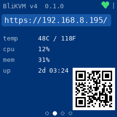
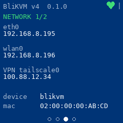
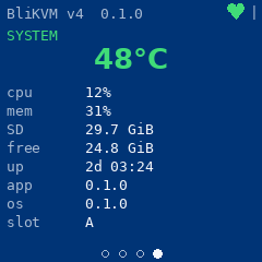
Illustrations generated from the current display drawing code, not device photographs. Addresses, versions and status are examples; labels may appear in the illustrated language.
See LCD / OLED display for always-on, startup-hold and interval settings. Display services vary by image. Older versions may only wake the display; two physical buttons alone do not establish provisioning support.
Wi-Fi provisioning without Ethernet
This procedure requires the newer v4 display provisioning service, NetworkManager and a matching wireless driver. Updating only the web app on an older image may not provide it. If provisioning does not appear, connect Ethernet and use web Wi-Fi settings, then check the installed image's feature notes.
- Attach the Wi-Fi antenna and stable power. Hold BUTTON 1 + BUTTON 2 together for about 3 seconds until the countdown and hotspot page appear.
- On your phone, join the temporary
BliKVM-xxxxhotspot shown on the LCD. Scan its Wi-Fi QR code or enter the displayed SSID and password manually. A new password is generated each time; illustration passwords do not work on real devices. - Stay connected if the phone warns of no Internet. If the setup page does not open automatically, browse to
http://192.168.4.1. This is a provisioning address, not the final KVM management address. - Choose your home / office Wi-Fi, enter its password and connect. Hidden networks support manual SSID entry. Rescanning may briefly disconnect the phone; reconnect as directed.
- The hotspot stops while BliKVM joins the target network, so phone disconnection is expected. On success, the LCD shows the new IP for about 5 seconds, then returns to overview.
- Join the same target network with the management computer or phone. Open the LCD's management address and verify page, video and input. Stop using
192.168.4.1after provisioning.
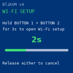
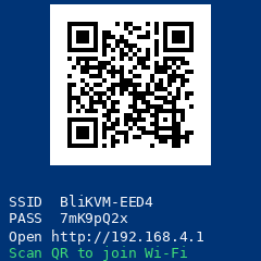
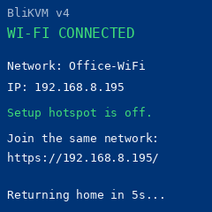
Provisioning illustrations, not device screenshots. SSID, password, QR code and IP are examples. If scanning fails, use the real display's SSID and password manually.
Failure, exit and recovery
- On connection failure, provisioning restores the hotspot. Check its current SSID / password on the LCD, reconnect and verify target credentials and signal.
- Choose Close hotspot and exit, or hold both buttons again for about 3 seconds, to exit. If connection was incomplete, the service attempts to restore the previous wireless connection.
- About 10 minutes without provisioning activity exits the hotspot. Automatic status refresh does not count as new activity.
- Provisioning temporarily interrupts existing Wi-Fi. Retain Ethernet if continuous management is needed. The setup hotspot does not share Internet access.
- For no hotspot, check the display state, antenna, image version and driver rather than guessing a fixed factory password.
Video modes
The current native H616 integration includes a hardware H.264 encoding path and MJPEG capture. Availability depends on the image's driver and hardware runtime. Follow Video modes and reported capabilities rather than the old software-H.264 description.
Check HDMI input limits, capture format and encoded network output separately. Maximum input specifications do not establish every mode's resolution or latency.
Packing List
| BLIKVM v4 | 1 |
|---|---|
| WiFi Antenna | 1 |
| ATX adapter board | 1 |
| ATX Dupont Cables 8pin Male to Male 60cm | 1 |
| ATX Dupont Cables 8pin Male to Female 60cm | 1 |
| 1U Rack Mounting Ears | 2 |
| M2.5x5 Screws | 8 |
| Silicone Bumper Pellets | 1 |
Serial Console Access via the 5V Port
The 5V port can be used both for power supply and serial console access at the same time. The default baud rate is 115200. There is an onboard CH341-based USB to UART converter present inside BliKVM v4 which is connected to UART0 of the mCore-H616 SoC, so you can connect a USB port of a PC to the 5V port without an external UART and a USB-C to dupont adapter.
Be careful when trying to use the 5V port because a PC USB port alone may not be able to provide 3A (5V) which is a documented requirement for the board to work. Either use a 12V 2A DC port at the same time as using the 5V port for serial communication without a USB Splitter board, or use the splitter board to split out the VCC pin and use a separate 5V 3A power supply to provide power to the 5V port's VCC pin. Likewise, when disconnecting a cable from the 12V 2A DC port while BliKVM is powered on, make sure to disconnect the cable from the 5V port first (because that will become the power source for BliKVM v4 after the 12V 2A source is disconnected unless a splitter is used).
You should see something like this in your host kernel log (if you are using a Linux-based OS) when attaching a USB cable to the 5V port of BliKVM v4:
usb 1-1.2: new full-speed USB device number 12 using xhci_hcd
usb 1-1.2: New USB device found, idVendor=1a86, idProduct=7523, bcdDevice=81.34
usb 1-1.2: New USB device strings: Mfr=0, Product=2, SerialNumber=0
usb 1-1.2: Product: USB Serial
ch341 1-1.2:1.0: ch341-uart converter detected
usb 1-1.2: ch341-uart converter now attached to ttyUSB0
Accessing this port can then be done using GNU screen or TIO:
tio /dev/ttyUSB0
mangopimcore login: blikvm
# ...
If you need to check how much data is received over UART0 you can do this by looking at the counters exposed via proc as follows (the rx counter should increase when the data is sent from an external host if the built-in USB to UART converter is working properly):
root@mangopimcore:~# grep '0: uart' /proc/tty/driver/serial
0: uart:16550A mmio:0x05000000 irq:284 tx:20306 rx:40 pe:1 RTS|DTR