ATX guide
This page covers ATXA installation, signals and wiring for compatible controllers. For BliKVM web operation see ATX power control.
Installation and checks
- Shut down and unplug the computer. Find power-button, reset and indicator pins in its motherboard manual.
- Connect board B to the matching signals, checking LED polarity. To retain case buttons, reconnect the case wiring using the dual-row diagram below.
- Connect board A to a compatible controller, checking power, ground and GPIO definitions, then link A and B. The RPI4 table below is a PiKVM example, not a universal BliKVM pinout.
- Restore power, test original case buttons, then planned controller short-press and reset actions. Use a forced long press only when needed.
The A / B RJ45 connectors carry ATX signals. Do not connect them to Ethernet switches or PoE equipment.
1. Introduction
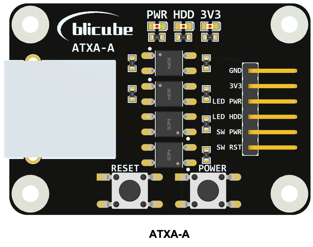
ATXA is an ATX adapter board to manage the power of your computer.
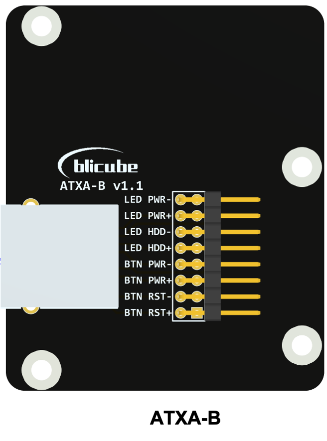
The product includes two modules; A-board and B-board. A-board is connected to the Raspberry Pi, B-board is connected to the computer's motherboard, and A-board is connected to B-board through a network cable.
Join the Discord Community Chat for news, questions and support!
| ATXA_A | ATXA_B |
|---|---|
 |  |
2. A-board
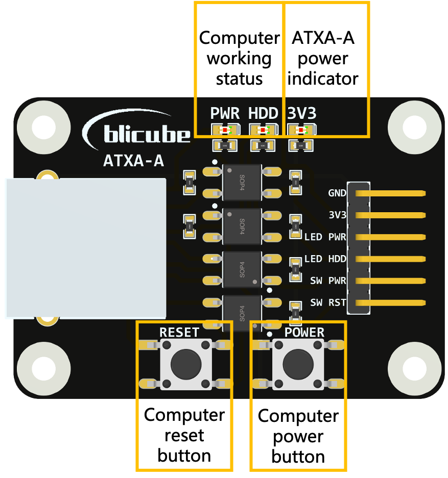
A-board is connected to the Raspberry Pi.
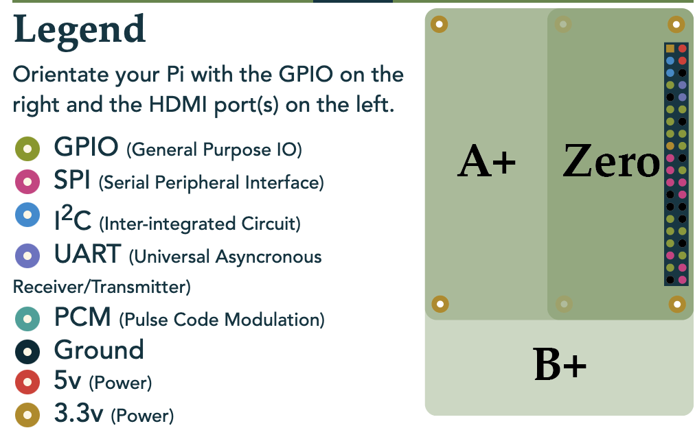
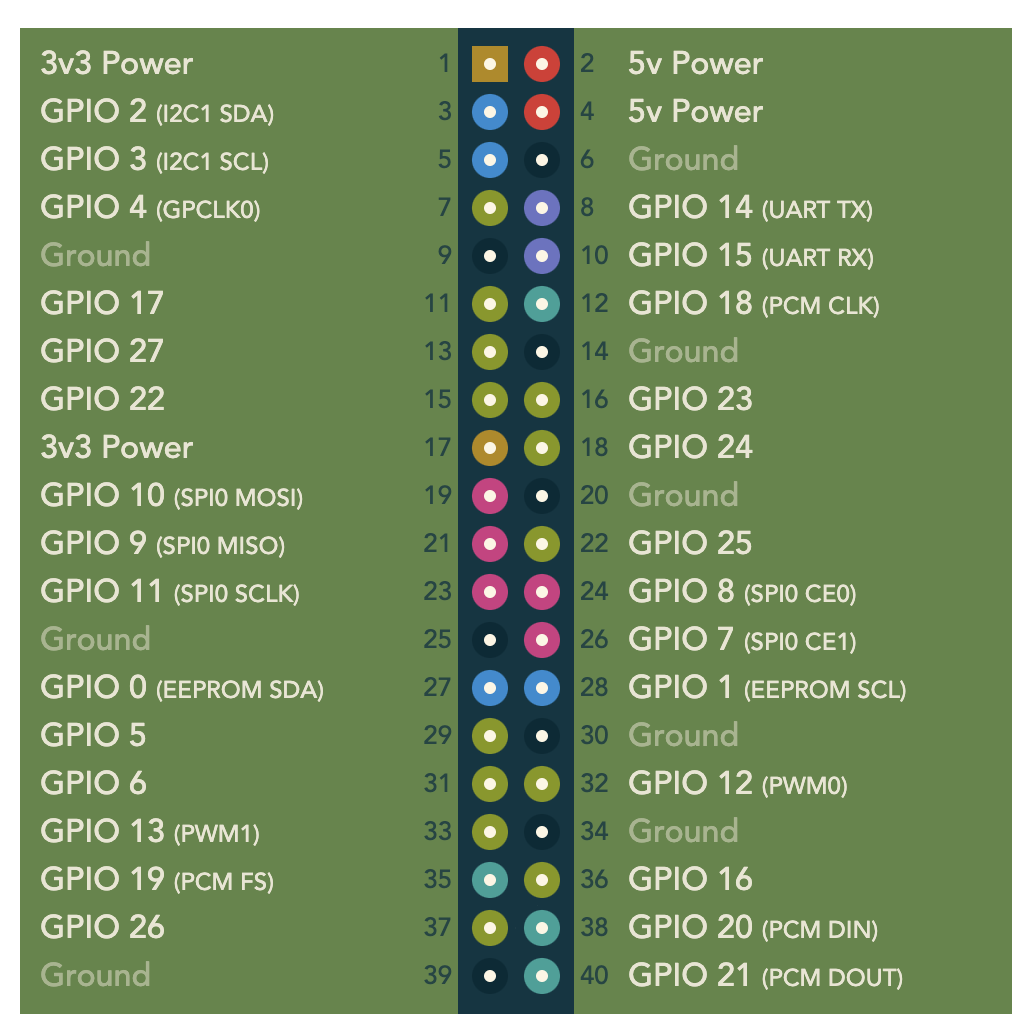
The following table is a typical connection method in PiKVM application.
| A-board | RPI4 |
|---|---|
| GND | GND |
| 3V3 | 3V3 |
| LED PWR | GPIO24 |
| LED HDD | GPIO22 |
| SW PWR | GPIO23 |
| SW RST | GPIO27 |
 |  |
A-board is connected to B-board through a network cable. The following table is the corresponding relationship between the pin status of A-board and B-board.
| Pins on A-board | Pins on B-board |
|---|---|
| LED PWR is HIGH | LED PWR+ is HIGH, LED PWR- is LOW |
| LED PWR is LOW | LED PWR+ is LOW, LED PWR- is LOW |
| LED HDD is HIGH | LED HDD+ is HIGH, LED HDD- is LOW |
| LED HDD is LOW | LED HDD+ is LOW, LED HDD- is LOW |
| SW PWR is HIGH | BTN PWR+ and BTN PWR- connected, the power button is pressed |
| SW PWR is LOW | BTN PWR+ and BTN PWR- disconnected, the power button is unpressed |
| SW RST is HIGH | BTN RST+ and BTN RST- connected, the reset button is pressed |
| SW RST is LOW | BTN RST+ and BTN RST- disconnected, the reset button is unpressed |
3. B-board
The b-board has an adapted full-height and half-height metal PCI mounting plate, which can be installed on the computer case. The user connects the pins on the B-board to the ATX control interface on the computer motherboard using the color DuPont cables provided with the product.
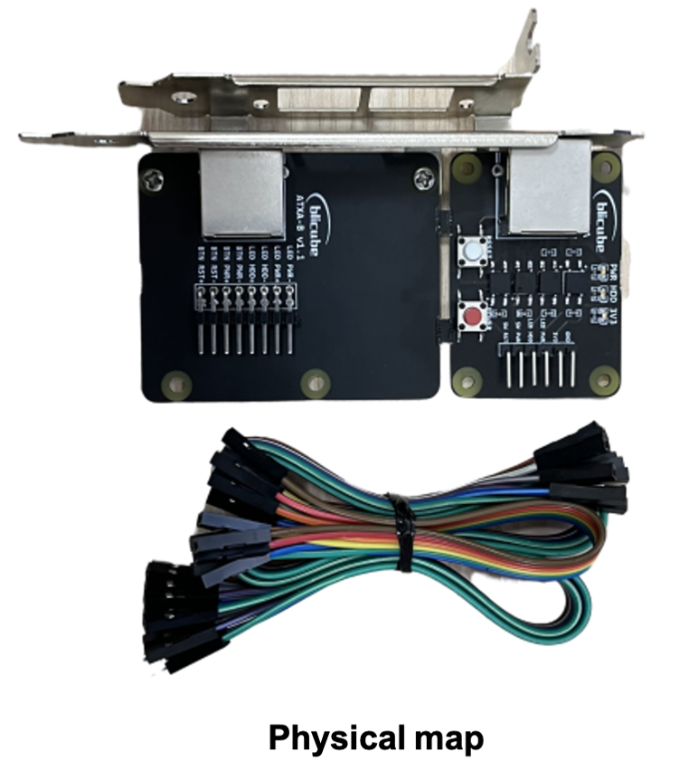
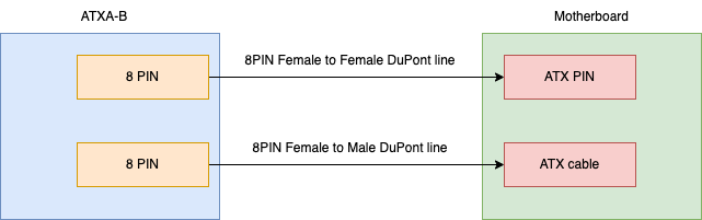
According to the instructions of the computer motherboard, first find the position of the ATX function related pins on the motherboard, and then unplug the ATX ray that has been connected to the motherboard. After unplugging, the power button of the computer will lose its function. There are two rows of 8PIN pins on the ATXA-B motherboard. It is unnecessary to distinguish between the two rows of pins when they are used with the same functions. One row of pins is used for KVM to control ATX-related functions, and the other row of pins is connected to the ATX DuPont head unplugged from the main board to maintain the original chassis power button function. Connect each wire according to the specific pin definitions on the motherboard and ATXA-B. See the following figure for the connection relationship:
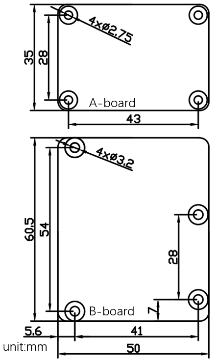
4.Mechanical Diagram
5. Test video
YouTube: ATX
6. Purchase
Purchase:ATX