BliKVM RK3566 (Beta)
This device is an internal testing (beta) model. Hardware, software, and documentation may change across releases. Long-term supply and support are not guaranteed.
If you need a stable, production-ready solution, please choose the standard BliKVM product line.
Hardware interface
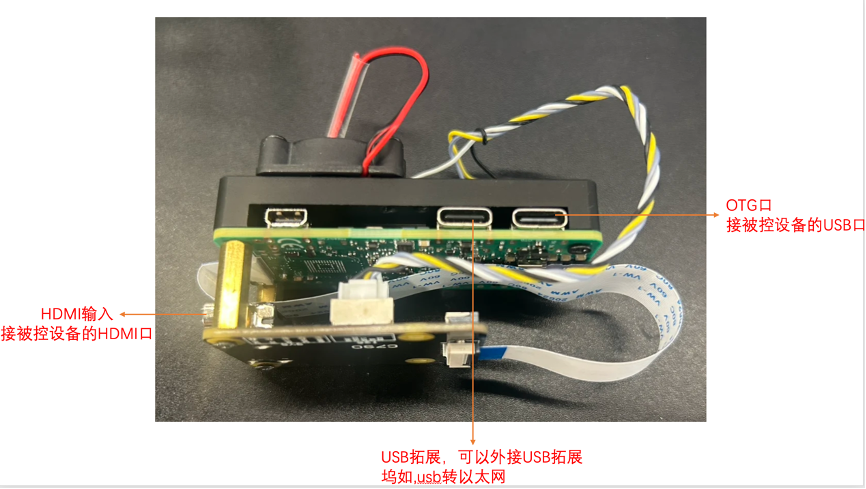
- HDMI IN: Connect to the target PC HDMI output for video capture.
- Type‑C (OTG): Connect to the target PC USB for keyboard/mouse/virtual media emulation. Also powers the KVM.
- Type‑C (HOST): Host port. You can connect a Type‑C hub (extra USB ports / USB Ethernet adapter, etc.).
In the box
- BliKVM‑RK3566‑Beta device × 1
- USB‑A to USB‑C data cable × 1
Note: HDMI cable is not included.
Key specifications
| Item | Spec |
|---|---|
| SoC / Memory | RK3566 / 1 GB RAM |
| Wireless | Wi‑Fi 6 |
| Storage | 32 GB TF |
| Capture & encode | Up to 1080p@60 capture and encoding |
| Encode modes | Hardware encode: H.265 / H.264 / MJPEG |
| Cooling | Fixed-speed fan |
Core features
- Video capture (HDMI, up to 1080p@60 encoding)
- Keyboard forwarding
- Mouse forwarding
- Microphone forwarding (two-way audio)
- Virtual Media (OS installation, bidirectional file transfer)
- ATX power control (with ATX accessory)
- Fullscreen mode
- Multi-language UI
- Wi‑Fi 6
- Switch integration (target switching)
- OpenAPI
- Wake on LAN (WoL)
- Custom HDMI EDID
- Custom HID device information
First boot (Wi‑Fi version)
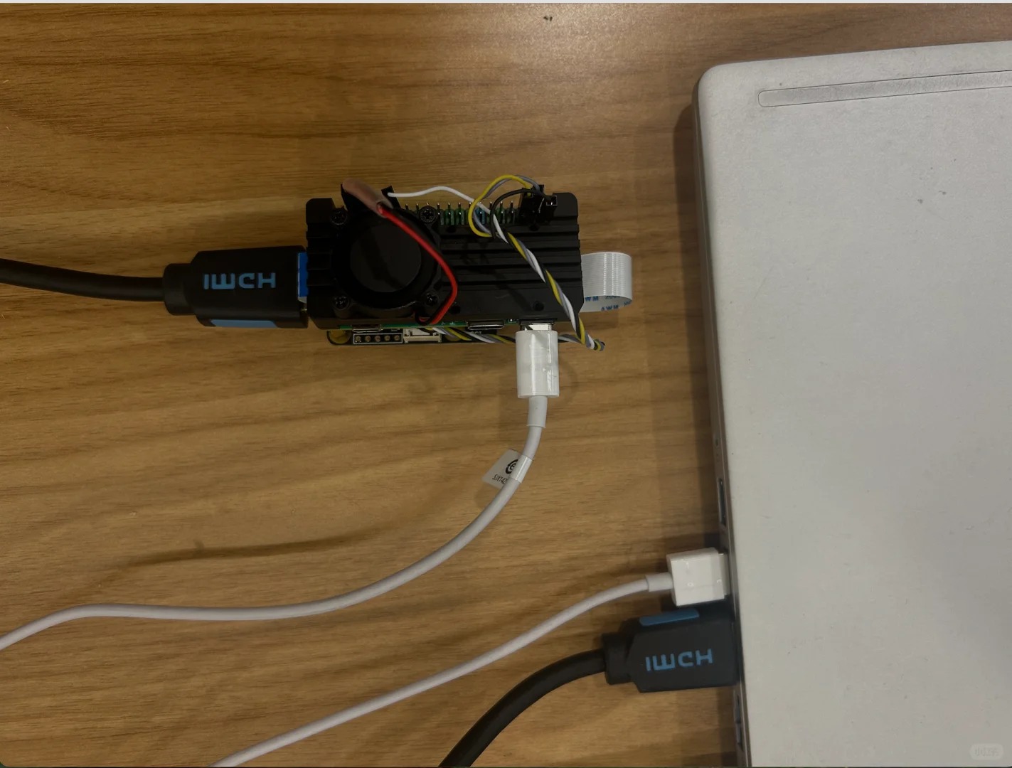
At minimum, you only need to connect an HDMI cable and a USB cable between the target device and the KVM.
Connect to the default hotspot
On first boot, the device starts a Wi‑Fi hotspot by default:
- SSID:
KVM - Password:
kvm12345
Connect to this hotspot from your computer, then open in a browser:
http://10.42.0.1(automatic redirect to HTTPS is normal)
Default accounts
- Web UI:
admin/admin - SSH:
root/BliKVM
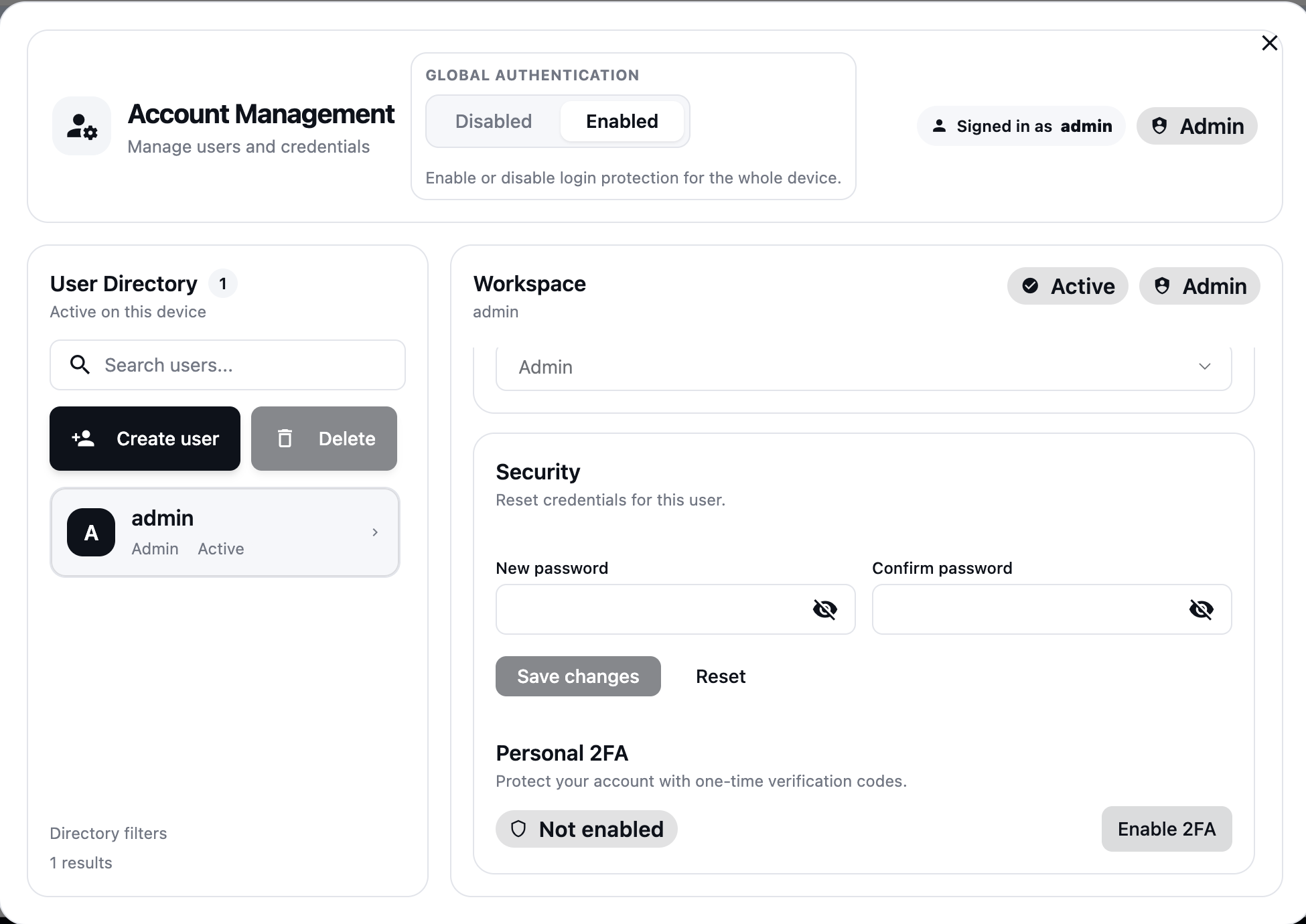
After your first login, change the default passwords immediately, and enable 2FA if needed.
ATX Power Control
ATX Guide
To enable ATX power control for your BliKVM-RK3566-Beta device, you need to connect the ATX accessory to the GPIO pins. The following table shows the complete 40-Pin GPIO mapping with ATX control functions:
40-Pin GPIO Interface
| function | number | Pin# | Pin# | number | function |
|---|---|---|---|---|---|
| +3.3V | 1 | 2 | +5.0V | ||
| GPIO1_A0 | 3 | 4 | +5.0V | ||
| GPIO1_A1 | 5 | 6 | GND | ||
| GPIO3_C4 | 7 | 8 | GPIO0_D1 | UART2_TX_M0 | |
| GND | 9 | 10 | GPIO0_D0 | UART2_RX_M0 | |
| GPIO3_A1 | 11 | 12 | GPIO3_A3 | ||
| RESET | GPIO3_A2 | 13 | 14 | GND | |
| LED_HDD | GPIO3_B0 | 15 | 16 | GPIO3_B1 | POWER |
| +3.3V | 17 | 18 | GPIO3_B2 | LED_PWR | |
| GPIO4_C3 | 19 | 20 | GND | ||
| GPIO4_C5 | 21 | 22 | GPIO3_C1 | ||
| GPIO4_C2 | 23 | 24 | GPIO4_C6 | ||
| GND | 25 | 26 | NC | ||
| GPIO4_B2 | 27 | 28 | GPIO4_B3 | ||
| GPIO3_B3 | 29 | 30 | GND | ||
| GPIO3_B4 | 31 | 32 | GPIO3_C2 | ||
| GPIO3_C3 | 33 | 34 | GND | ||
| GPIO3_A4 | 35 | 36 | GPIO3_A7 | ||
| GPIO1_A4 | 37 | 38 | GPIO3_A6 | ||
| GND | 39 | 40 | GPIO3_A5 |
Serial Terminal
When the device has problems and loses network connectivity, before reflashing the system, you can try to access the system via serial terminal. You need to use a USB-to-TTL serial cable to connect UART2_TX_M0 and UART2_RX_M0.
There is no password for the serial terminal, simply press Enter to enter.
The default serial configuration is as follows:
baudrate: 1500000
data bit: 8
stop bit: 1
parity  : none
flow control: none
Web UI quick start
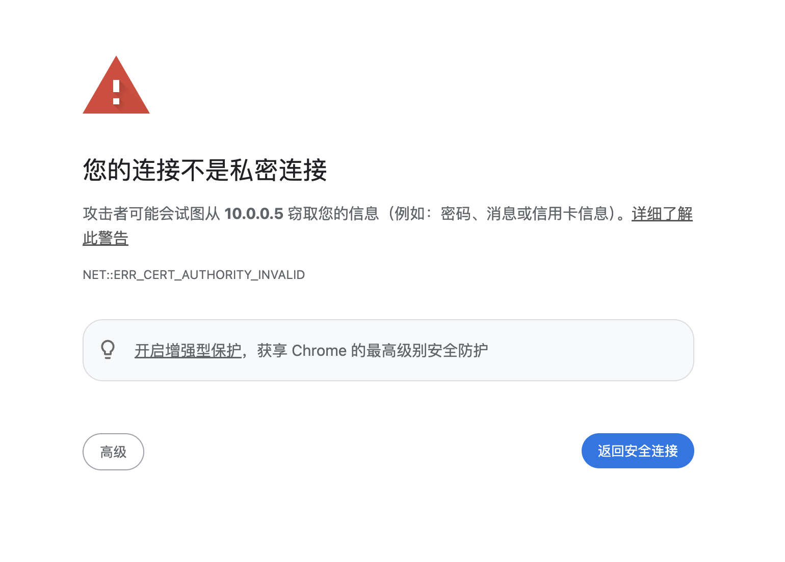
Certificate warning (first visit)
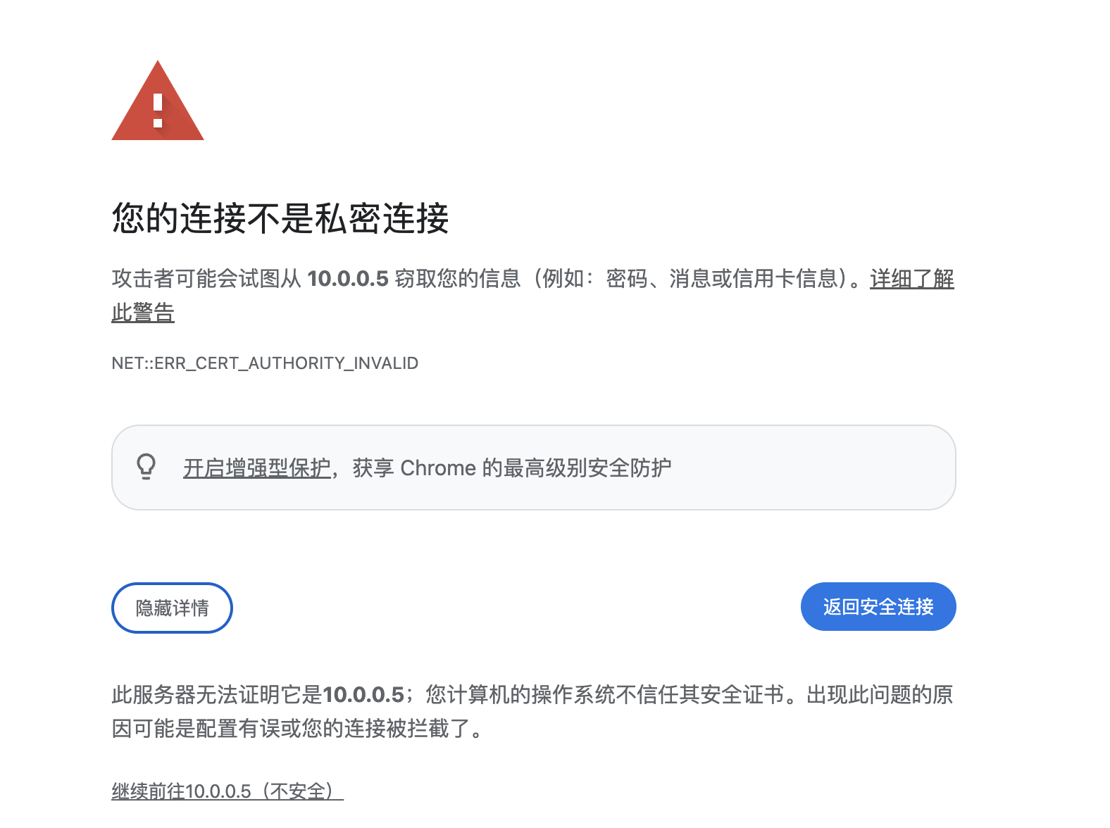
If your browser warns that the connection is not private, it is usually because the device uses a self-signed certificate. Click Advanced and proceed to continue.
Login page
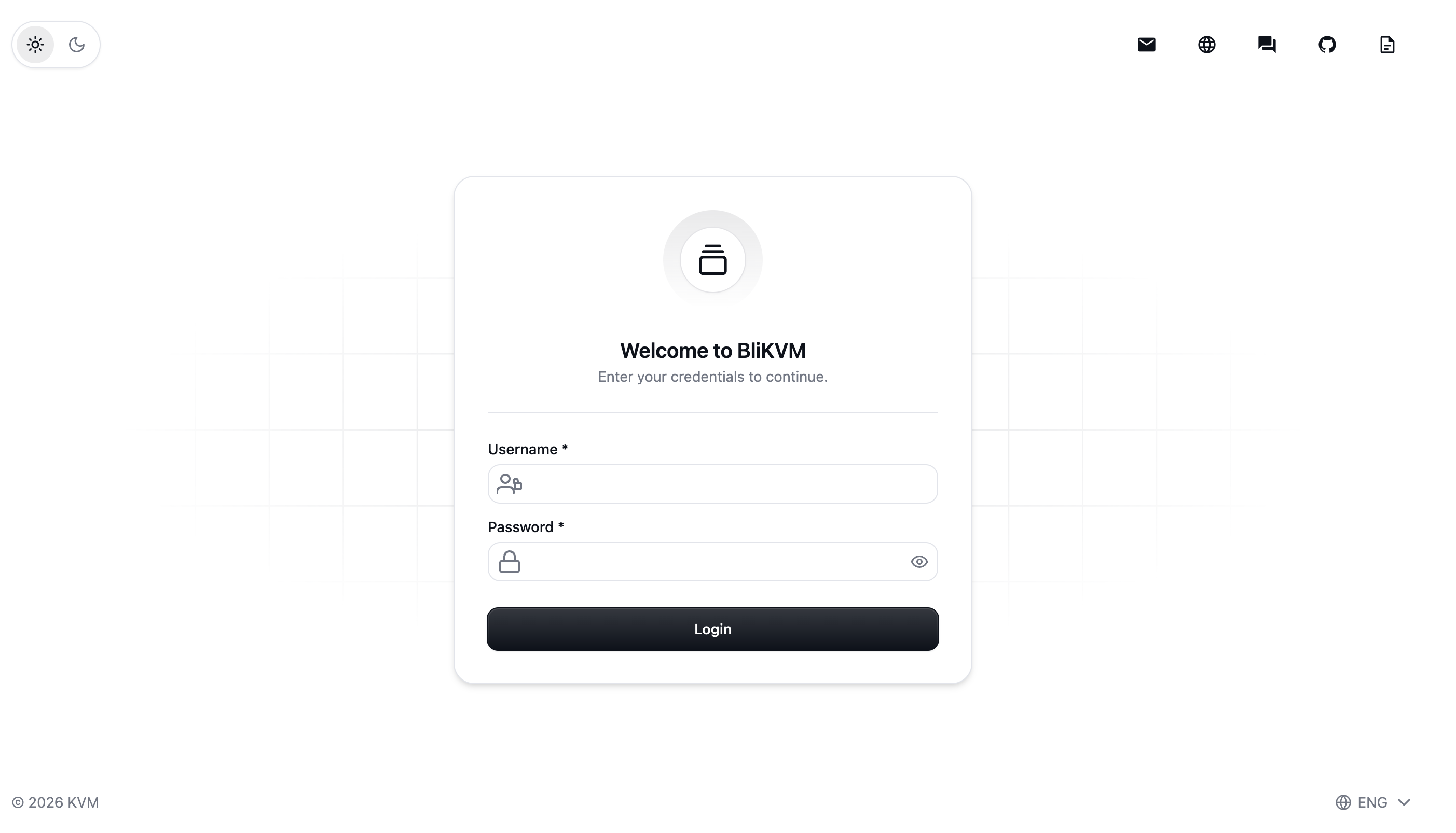
Enter your username and password to log in. If 2FA is enabled, you will see an additional 2FA verification input.
Main page & common tools
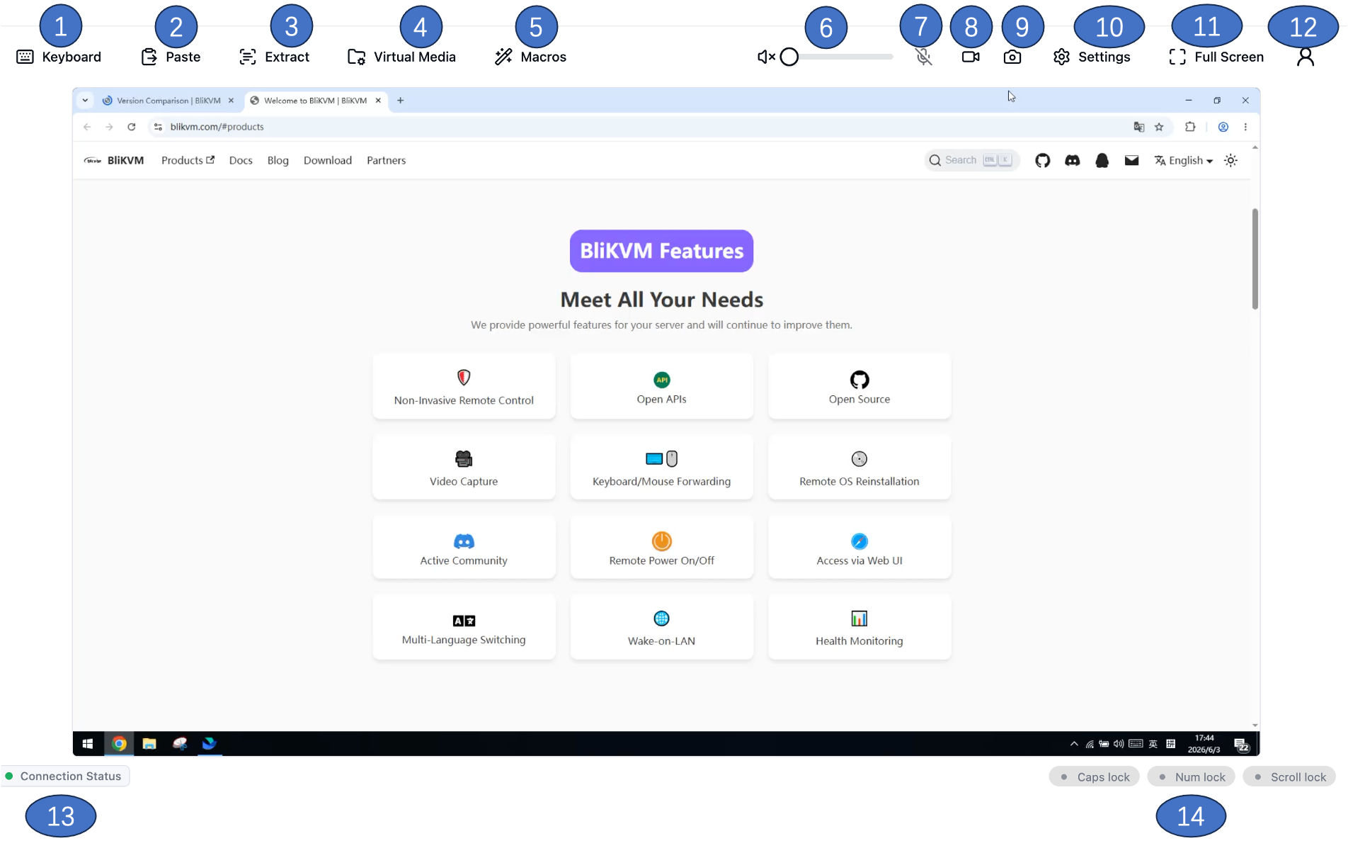
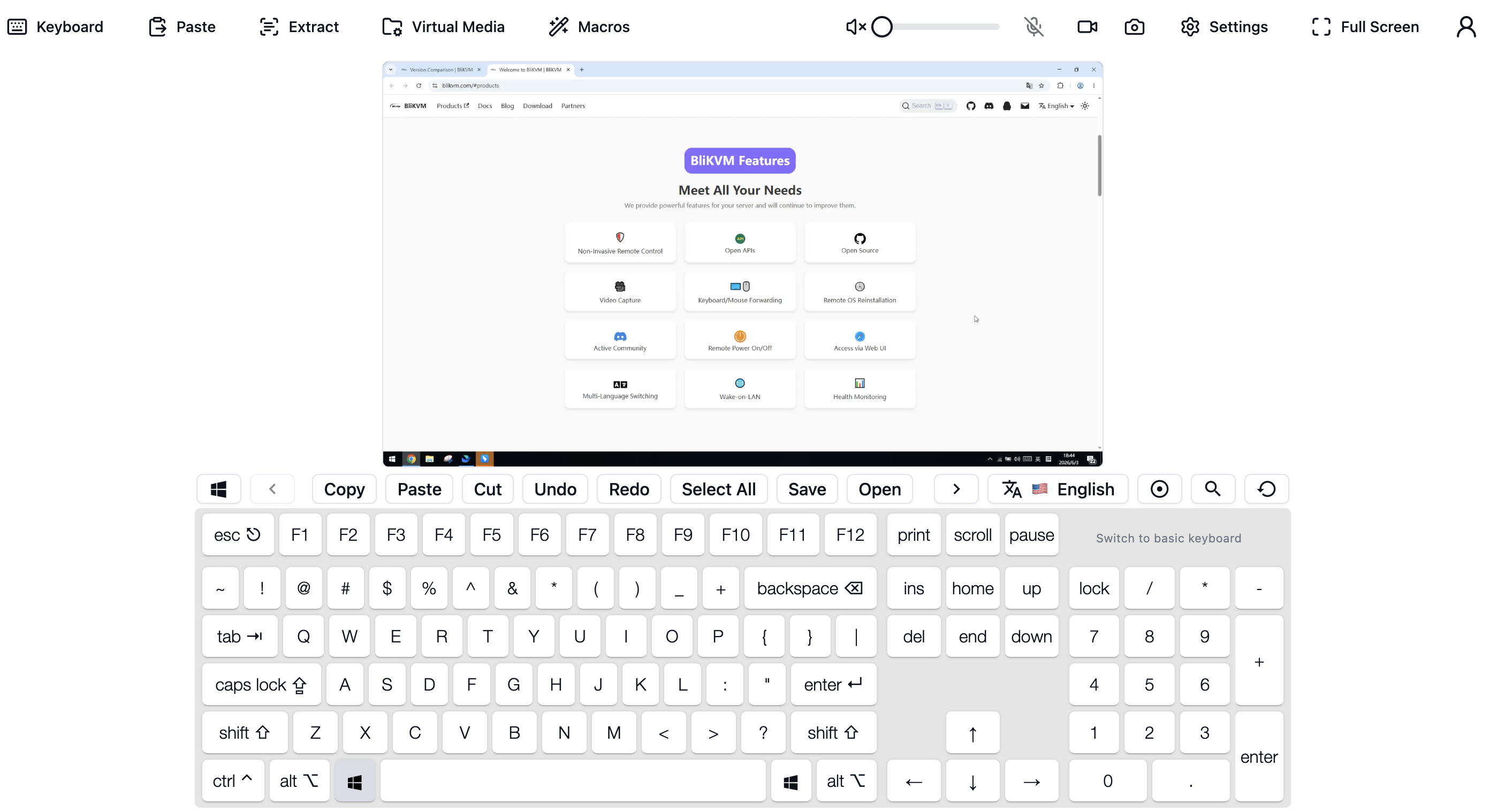
- Virtual keyboard
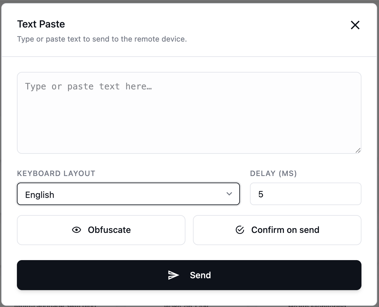
- Quick paste text
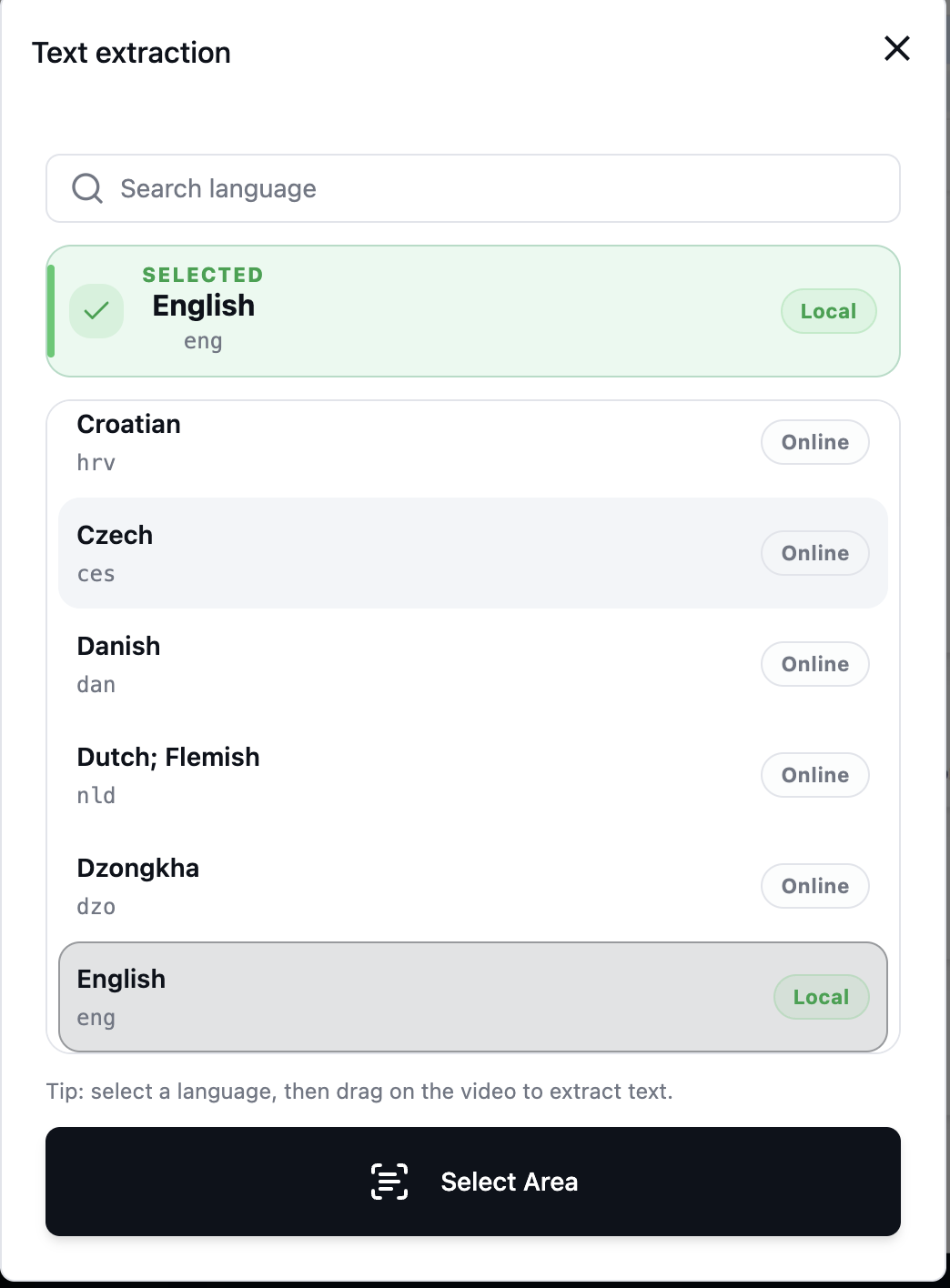
- OCR text extraction
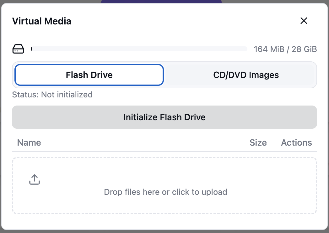
- Virtual Media: for OS installation and file transfer with the target device.
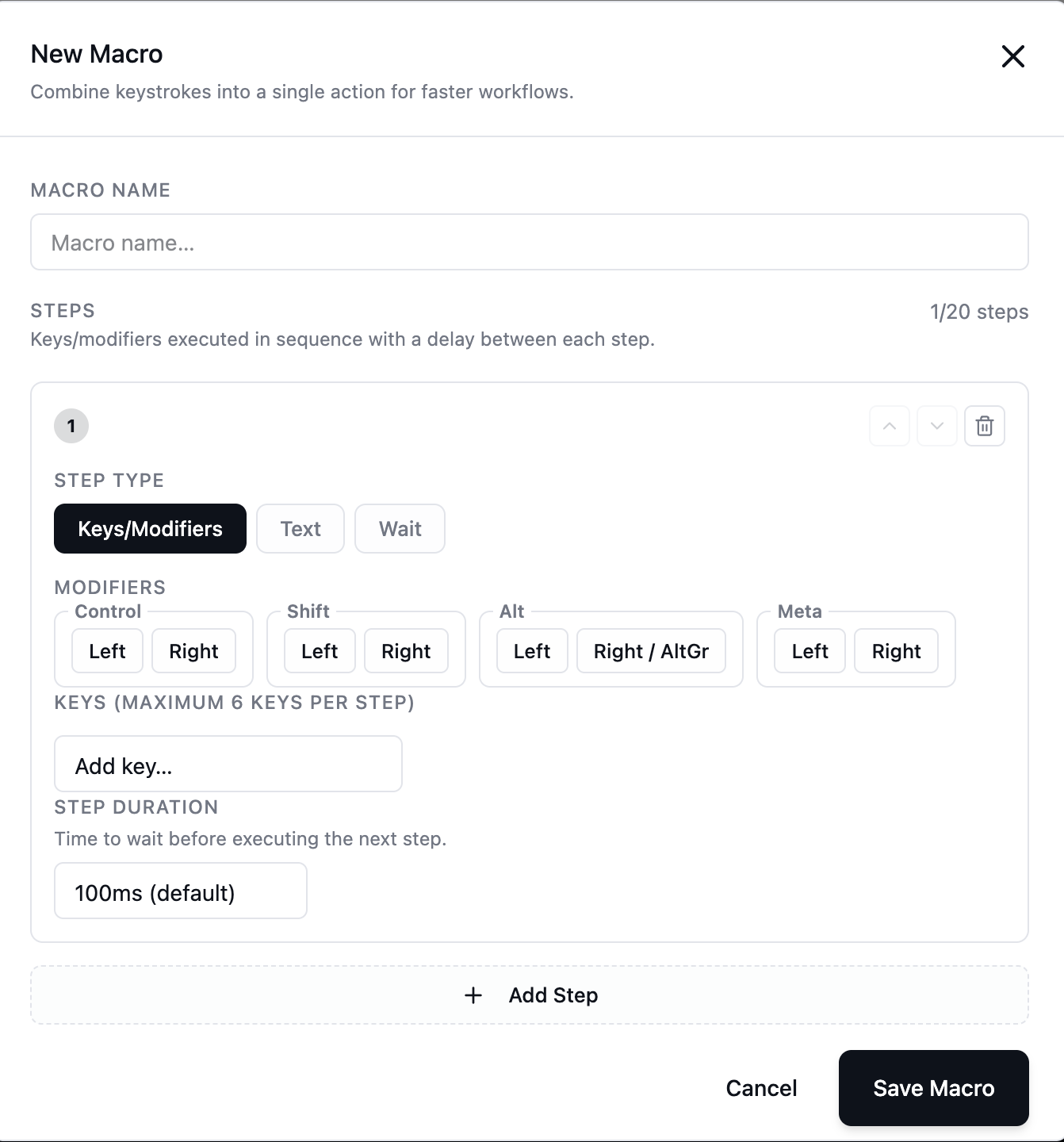
- Keyboard macros
Other tools (depending on your build):
- Video volume control
- Microphone input toggle: capture audio from the controlling side and emulate it as a “microphone device” to the target over OTG (useful for remote meeting scenarios)
- Video recording
- Screenshot
- Settings
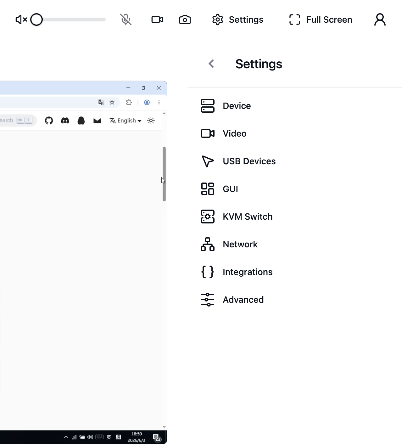
- Fullscreen
- User management & system upgrade
- Connection status
- Keyboard status
Network settings
Wi‑Fi
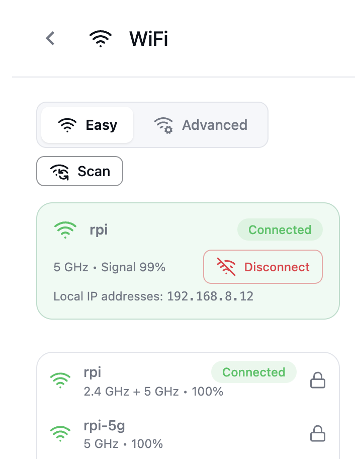
- Connect to Wi‑Fi directly from the UI.
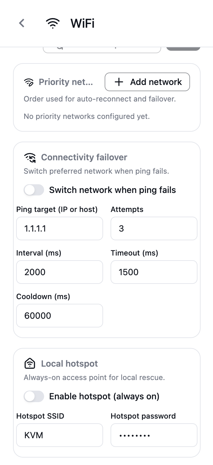
- Multiple Wi‑Fi profiles are supported; if one Wi‑Fi disconnects, it can switch to another available profile automatically.
- Hotspot mode is supported.
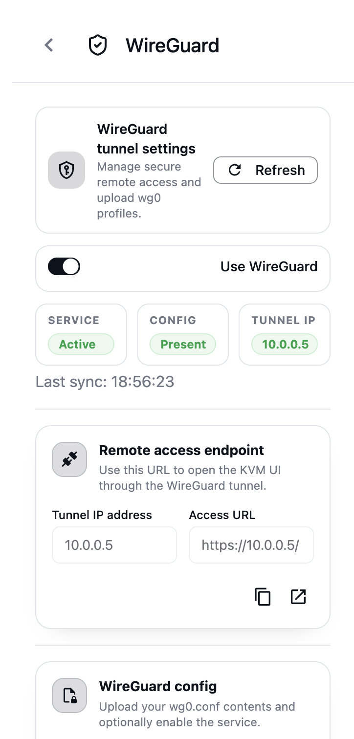
WireGuard
WireGuard is included in the base image. You can enable it by uploading your WireGuard config file.